Focus on providing solutions for outdoor digital media and LED industrial applications

| Place of Origin: | China |
|---|---|
| Brand Name: | Sysolution |
| Certification: | RoHS,CE-EMC |
| Model Number: | D60-75 |
| Minimum Order Quantity: | 1 |
| Price: | 9 USD |
| Packaging Details: | carton box |
| Delivery Time: | 2-3 working days |
| Payment Terms: | T/T,PayPal |
| Supply Ability: | 30 units per week |
| Three Parallel Lines (RGB): | 24 Group | Maximum Load (Pixels): | 512*256 |
|---|---|---|---|
| Brightness Correction Band Load (Pixel): | 512*256 | Chromaticity Correction With Load (Pixels): | 256*320 |
| Support Scan Line: | 1-64 Scan | Input Voltage: | DC3.5-5.5V |
| Rated Current: | 0.6A | Rated Power: | 3W |
| Working Temperature: | -20℃-70℃ | Working Humidity: | 10%RH-90%RH |
| Board Size: | 144.02mmX91.2mm | Net Weight: | 100.8g |
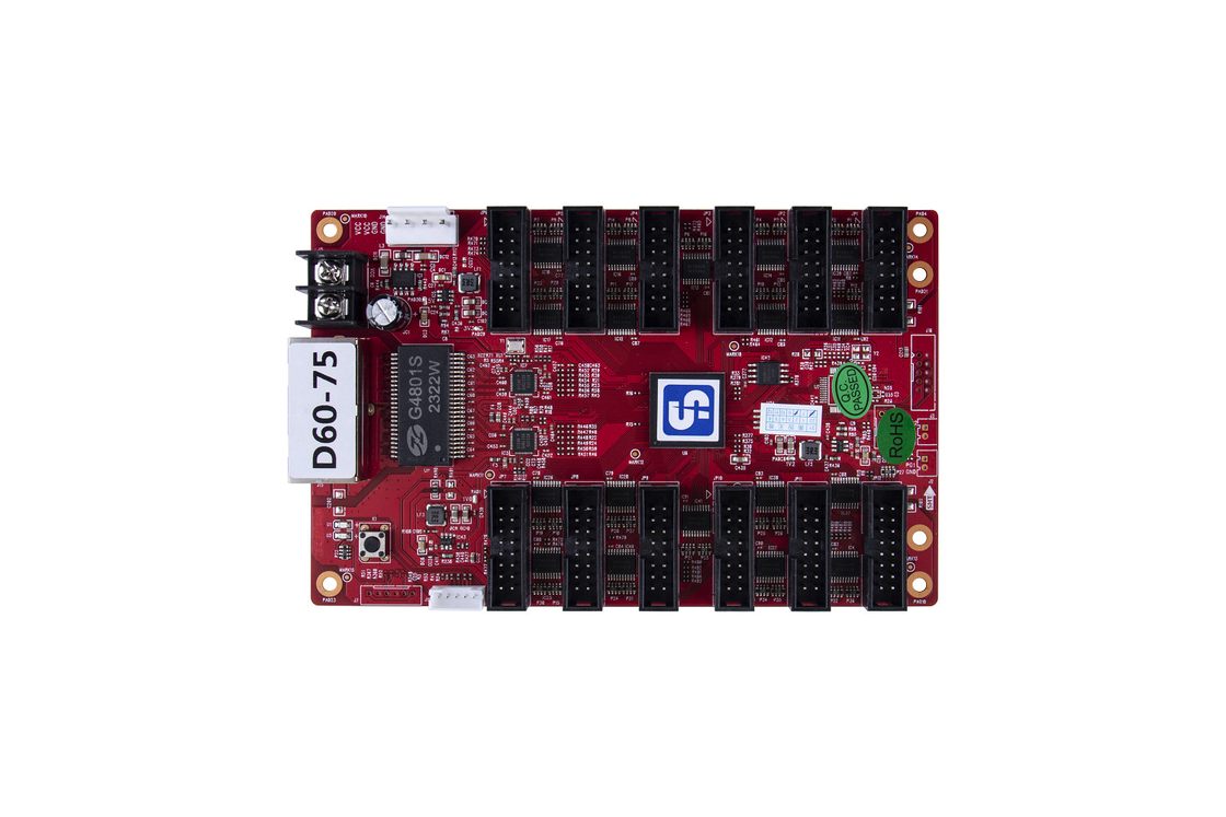
D60-75 is a receiving card launched by Sysolution Technology.It adopts 12 standard HUB75E interfaces and supports up to 24 groups of RGB parallel data; The load is up to 512X256 pixels; It has powerful processing capabilities, ultra-stable performance and high cost performance.
| Three parallel lines(RGB) | Data interfaces | Driving |
Maximum load(Pixel) |
Brightness correction band load(Pixel) | Chromatic correction with load(Pixel) |
| 24 group | HUB75E/12 | General | 512*256 | 512*256 | 256*320 |
| PWM | 512*256 | 512*256 | 256*320 |
| Number of cascade cards |
|
|||
| ≤1000PCS | 1-64 Scan |
| Function | Instructions |
| Improved Display Effect |
|
|
Improved Operability |
|
| Improved Hardware Stability |
|
|
Intelligent Software Upgrade
|
|
24 Parallel Data Interface Definitions
![]()
JP1-JP12 Data Interface Definition
| Description | Definition | Pin | Steward | Definition | Description |
|
RGB Data Output |
R | 1 | 2 | G | RGB Data |
| B | 3 | 4 | GND | earth (electric connection) | |
| R | 5 | 6 | G | RGB Data | |
| B | 7 | 8 | E |
line decoding signal |
|
| line decoding signal | A | 9 | 10 | B | |
| C | 11 | 12 | D | ||
| Shift Clock | CLK | 13 | 14 | LAT | latching signal |
| Display Enable | OE | 15 | 16 | GND | earth (electric connection) |
Note 1: Pin 15 is the display enable pin. When using PWM chip, it is GCLK signal.
J16 Definition:
| Definition | Pin | Steward | Definition |
| +5V | 1 | 2 | GND |
| FLS_CS | 3 | 4 | FLS_DO |
| FLS_CLK | 5 | 6 | FLS_DI |
| PROGRAM_B | 7 | 8 | mCONF_DONE |
| GND | 9 | 10 | +5V |
J12 Indicator Interface Definition:
| Pin | 1 | 2 | 3 | 4 | 5 |
| Definition | GND/KEY- | KEY+ | LEDR- | VCC/LED+ | LEDG- |
J14 Power Socket Definition:
| Pin | 1 | 2 | 3 | 4 |
| Definition | VCC | VCC | GND | GND |
| Indicators | Location | State | Description |
|
Status indicator (green) |
U1 | Flashes evenly and slowly |
The receiving card works normally, the network cable is connected normally and there is no DVI signal input. |
| Flashes evenly and quickly | The receiving card works normally, the network cable loop is connected, and there is DVI signal input. | ||
| Off | No Gigabit network signal | ||
| Flash 3 times at intervals | The receiving card works normally, the network cable loop is connected, and there is DVI signal input. | ||
|
Status indicator (red) |
U3 | on | Normal power supply |
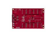
Dimension:
![]()
| Electrical parameters | Input voltage | DC3.5-5.5V |
| Rated current | 0.6A | |
| Rated power | 3W | |
| Working environment | Working temperature | -20℃ - 70℃ |
| Working humidity | 10%RH-90%RH | |
| Storage environment | Temperature | -25℃~125℃ |
| Board size | 144.02mmX91.2mm | |
| Net weight | 100.8g | |
| Certification Information | RoHS compliant, CE-EMC compliant |
|